divtiesus_maple
DivTIESUS Maple Edition
DivTIESUS Maple Edition is a SD/MMC card interface for the ZX Spectrum. It is based on Miguel’s DivTIESUS, but adds joystick port and serial port for WiFi at the expense of Soft +3E feature. I redid whole project in KiCAD and rerouted the PCB. CPLD pin assignment has been changed to accommodate new PCB layout.
You can buy me a coffee if you want to say thank you.
Features
- DivMMC compatible interface with 8 KiB of EEPROM and 128 KiB or 512 KiB of RAM. Standard utils for EEPROM flashing, as provided by the ESXDOS team, are compatible with DivTIESUS.
- Model autodetection. This means you don’t need to put a jumper, or flip a switch to change from using it with a Spectrum 48K and a +3.
- Tested with original Spectrum+, Black +2, Harlequin 128 rev. 2D and rev. 4B, Karabas 128 rev. B1. More testing reports will be appreciated
- It uses its own fast clock (24 MHz). It does not need the CPU clock at all.
- NMI button to call file browser in ESXDOS, and handy RESET button.
- MicroSD card slot
- DIP switches for enabling EEPROM flashing and disabling auto-mapping (bottom switch) and for disabling built-in joystick interface (top switch)
- Optional: Zx-Uno-compatible UART (running at 115200 baud) with WiFi. Do not place ESP12 if you are not planning to use it
- Optional: Built-in Kempston joystick interface, compatible with either Atari-style joystick or Sega Genesis joystick (3 or 6-button). Do not place DB9 connector and U6 (74HC165) if you are not planning to use it and disable it with a DIP switch. All 3 buttons are implemented (so called “extended Kempston”)
- Joystick interface maps “A” button as “UP” if “Start” button is pressed during machine reset.
- Visual feedback for SD activity (blue led)
- ESXDOS shadowing does not collide with all-RAM feature in +2A/B/3 machines. If the system is in all-RAM mode, ESXDOS ROM mapping is disabled.
- Included STLs for 3D printing an enclosure
Pictures


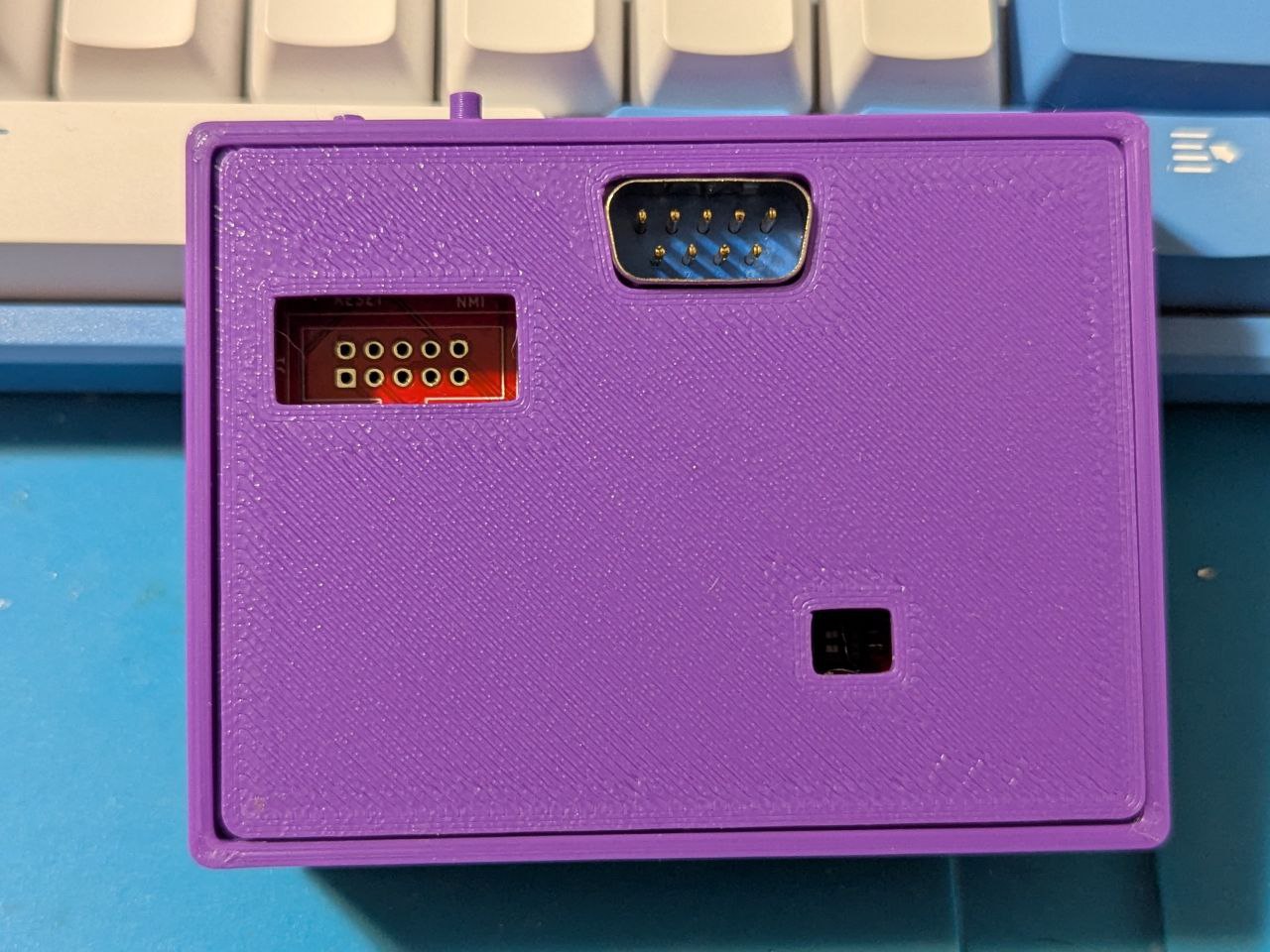
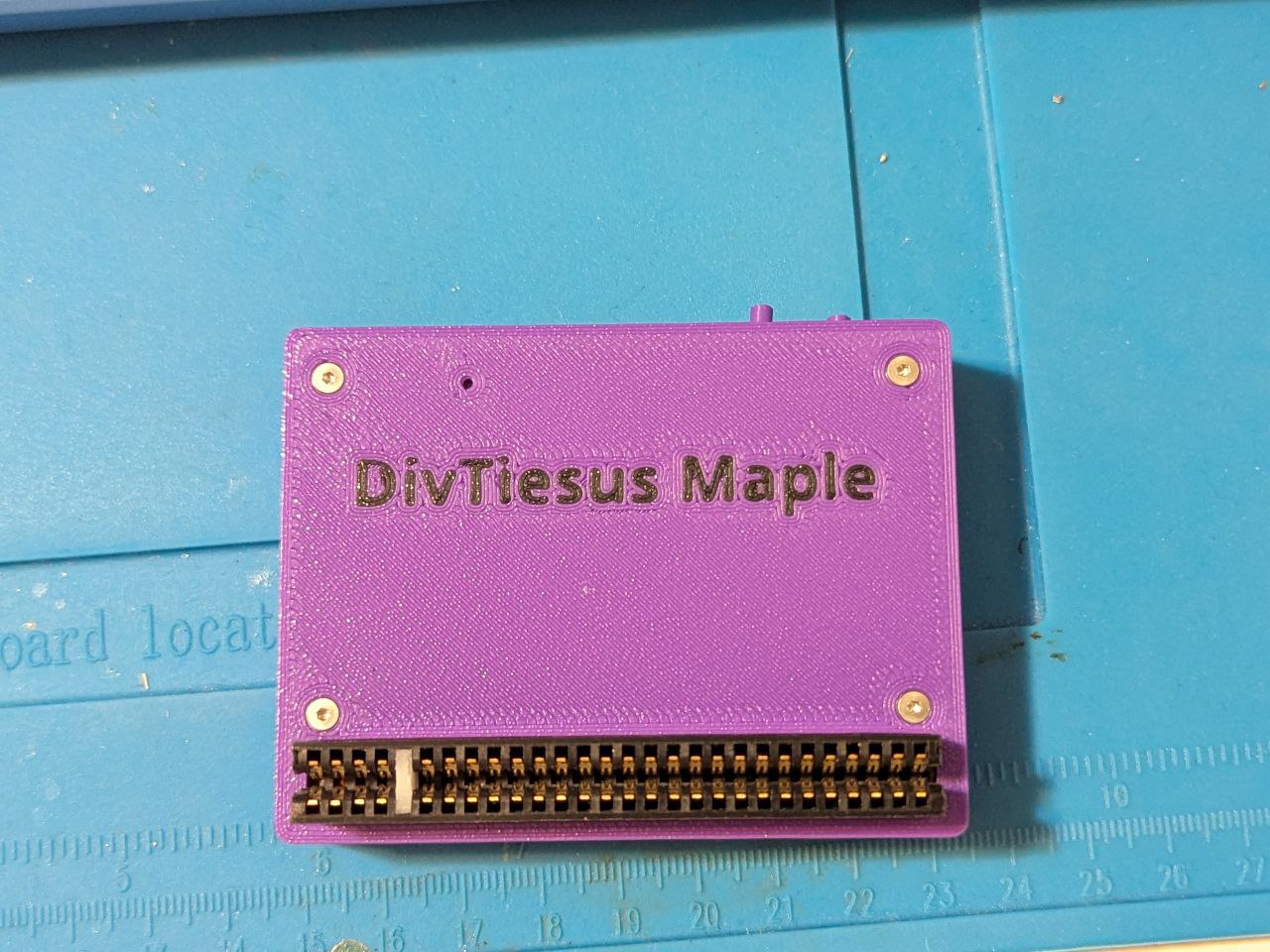
Schematic
Schematics can be found here
Build
- First, you need the DivTIESUS Maple Edition PCB. You can order it from JLCPCB or from PCBWay using
divtiesus_maple_rev2.zipfile from out directory. There is also a project on PCBWay if you want to support me - Second, source the components. Most of the components are rather standard so you can buy it off DigiKey or Mouser. All of them can also be obtained from AliExpress. Be careful with components from Aliexpress, especially if the price is too good to be true
Bill of materials
Interactive BOM can be found here
Links to some components:
| Qty | Component | Link |
|---|---|---|
| 1 | EPM240T100 | link |
| 1 | DIP switches, 2 position | link |
| 1 | RAM | link |
| 1 | EEPROM | link |
| 1 | ZX Bus connector, 56pin | link |
| 2 | Buttons, 6x6x6H | link |
| 1 | microSD slot | link |
| 1 | Crystal oscillator, 24Mhz | link |
- The oscillator does not need to be 24 MHz, but if you use a different value, you’ll have to resynthesize CPLD image, otherwise WiFi will not work
- I usually start with placing the CPLD first and programming it. Note: you’ll need to supply 3.3V in order to program CPLD, there are GND and 3.3V test points left for this purpose. I source CPLDs from Aliexpress and some of them are coming dead. It is easier to test and replace it before the rest of the components are populated.
- Then place the passives (resistors, resistor arrays, capacitors) and the LED
- Then RAM, EEPROM, microSD socket, DB9 connector and ESP12. You can either leave EEPROM blank or preprogram it. Either way is fine, it can be programmed in-system later, but having EEPROM with known contents may simplify troubleshooting
First electrical testing
- Check that there is no shorts on the 5V and 3.3V power rails.
- Use a microscope or a magnifying glass to check that there is no shorts between adjacent pads at the CPLD chip.
After all the checks, proceed to build and solder the ZX Spectrum bus connector:
ZX Spectrum bus connector
- Take the 2x28 pin edge connector and cut about 1-2mm on each side to leave the ends opened, refer to original DivTIESUS README.
- Pull and extract the two metal contacts that are positioned at 5th place, where the index tab will be placed
- Now take a small piece you can get from a PCB, 1.5mm thick and 7mm tall. This will be the index tab.
- As an alternative, you can 3D-print the tab, you can find the model here
- Place the tab in the index hole. Sand it if it’s too tall for the hole.
- Using a pair of pliers, push it in place. If it’s too small for the hole, use some glue to keep it from coming loose.
Now the edge connector is ready to work as a ZX Spectrum rear bus connector!
Enclosure
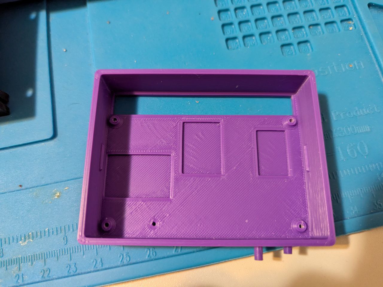
Enclosure can be printed in pretty much any plastic. You need button-2-nmi.stl, button-2-reset.stl, enclosure.stl and enclosure_top.stl or enclosure_top_no_jtag_no_switch.stl if you don’t want the holes for JTAG and the switch. Personally, I printed the parts in PLA and PETG. ABS should work as well. Keep in mind that PLA will soften at ~60C, so avoid using it for enclosure if you are planning to use the device with an original machine. Modern clones are fine, they are usually using CMOS ICs and modern voltage regulators that do not produce much heat.
First, place the buttons, short button (reset) closer to the edge
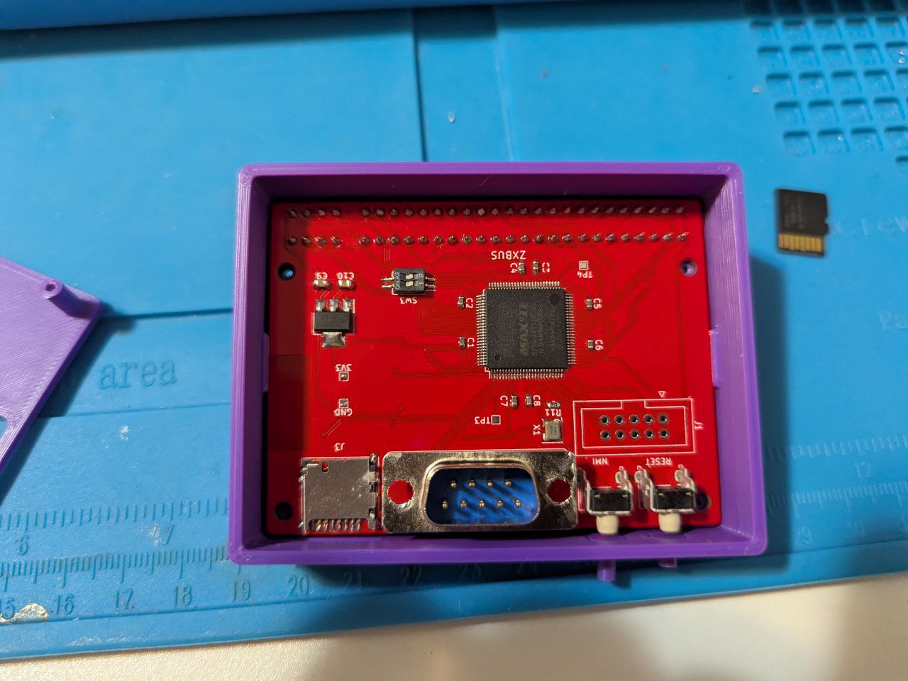
Then insert the PCB. Be careful to keep it straight and don’t let the buttons to fall out
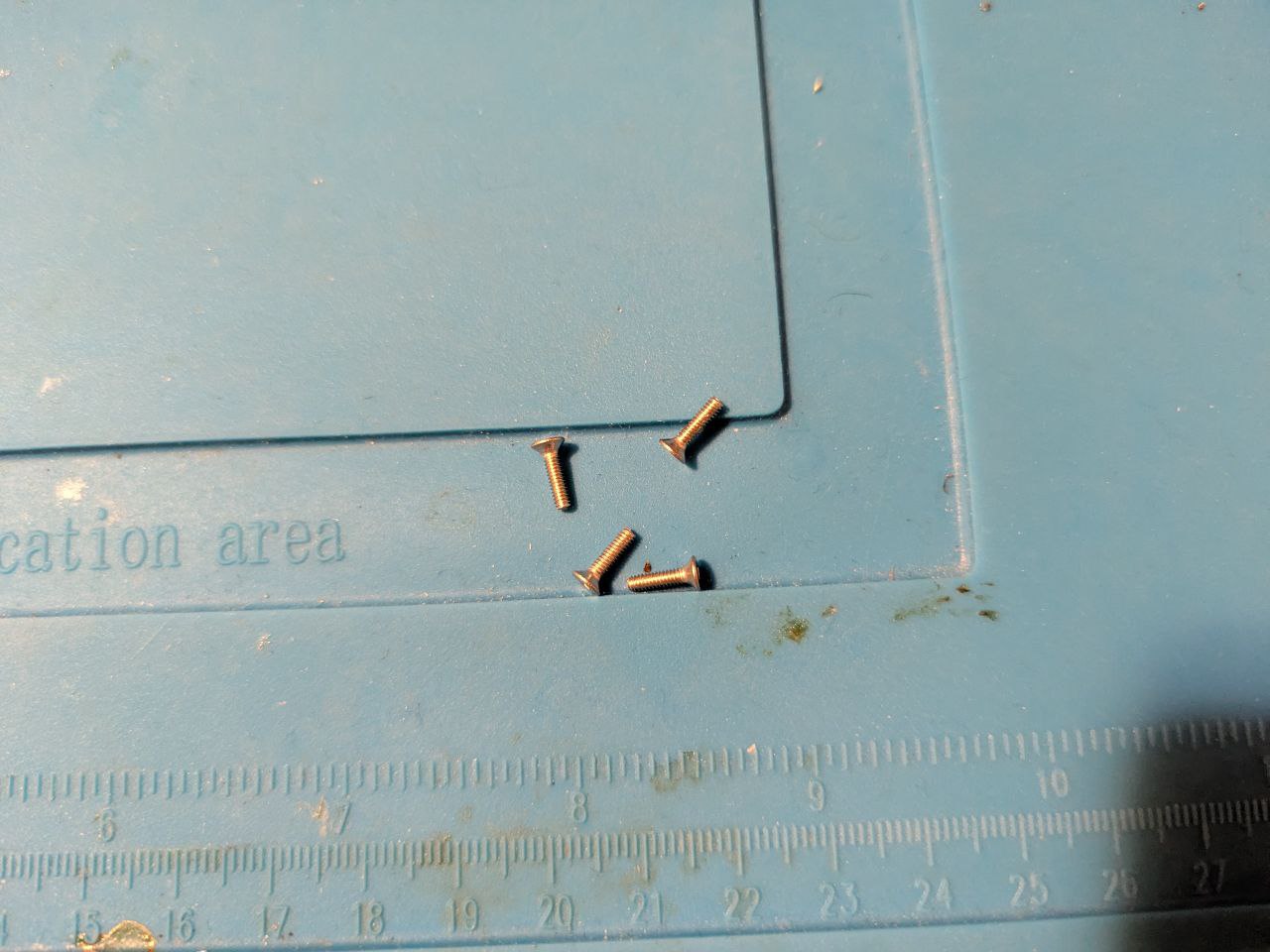
Use 4 M2x8 screws to fix enclosure top

WiFi
DivTiesus Maple Edition implements Zx-Uno-compatible UART, so software compiled for Zx-Uno should work with it.
I recommend using Nihirash’s software, Netman and Moon Rabbit. The binaries can be found here - just unpack them onto your SD card and run netman/NETMAN.BAS to configure WiFi. WiFi configuration is persistent, so it needs to be done once. Once WiFi is configured you can run moon_rabbit/MOONR.BAS to browse gopher sites.
You can also check out my tool for transferring files from PC to Spectrum: zxmit